Sunday, 1 January 2017

STRESS AND STRAIN

STRESS:
                 Stress is defined as the force per unit area and strain is the fractional change in length, area or volume. Obviously, this is the resistance of the body to deformation due to the application of external force.

              Stress describes the intensity of a force that acts on a unit area. Its units are N/mm2 or N/m2 . which is called pascal in SI Units and denoted by pa. When the force acting over an area is uniformly distributed, we have

            In several cases, such uniformly distributed loads are not present and therefore stress is non-uniform. This is why, the stress is always referred to a point and in a body the stress varies from point to point over any section. If F is the total load acting on the original cross-sectional area , then normal stress, 

                Obviously, stress is the intensity of internal force. The stress is said to be normal if load p is normal to the surface and tangential or shearing, if load is tangential to this surface. The normal or direct(tensile or compressive) stress is produced over a section when force is acting normal to the section. If the force is acting away from the section, the stress is tensile, if it is acting towards the section the section is compressive.

In general, the stress at any point will have six components and its nature is different than that of force and area both. In fact, stress at a point is a tensor quantity and needs the following specifications for complete specification: 
 (i) Magnitude  
(ii) Plane passing through the point, on which stress is being defined and,
(iii) The direction in which stress is acting.


STRAIN:
                Strain is the deformation produced per unit length of a body due to the effect of stress on it. It is the ratio of the change in length of the specimen to its original length. If L is the original length of the sample and  l is the change in length, then
            Strain is simply a ratio and has no unit and it is a dimensionless quantity. Depending upon the type of load, strain can be lateral strain or shear strain.
As there are different types of stresses, thee are different types of strains, e.g., 
                  (i) Compressive strain,
                  (ii) Shear or Transverse strain and
                  (iii) Volumetric strain.

    The strain associated with the change in length is called the elongation strain (l/L).Similarly  v/V  is the volumetric strain, where V is the volume. When there is a change in shape and no change in volume, corresponding strain is called shear strain. The shear strain is measured by the angle. The behavior of a material within the elastic limit is the same under compression as under tension.
Corresponding to elastic and plastic properties of materials, we have two classes of strain; (a) Elastic strain and (b) Plastic strain

(a) Elastic strain: It is the change in dimension of a body when it is subjected to a load. This is reversible phenomenon, i.e., elastic strain disappears after the applied load is removed. This is proportional to the stress applied.

(b) Plastic strain:  This is the permanent change in the body when subjected to a load. The change remains even after the applied load is removed.
The amount of elongation, expressed as a percentage of the original gauge length is called as the percentage elongation;
 

HOOKE'S LAW

                  In 1678, Robert Hooke, for the first time suggested that within elastic limits, stress is directly proportional to strain, i.e.,
   F µ e
Þ F = ke

The ratio of stress to strain is a constant characteristic of a material, and this proportionality constant is called modulus of the material. It differs from material to material, and for different nature of stresses.

When the stress applied is tensile or compressive, the constant is called Young's modulus of elasticity. The slope of stress-strain diagram up to the limit of proportionality is called Young's modulus of elasticity (Y or E).


When shear stress and strain are used, it is called modulus of rigidity (G). It is given by

TESTING OF MATERIALS

Introduction:

Metals are  tested for one or more of the following purposes:
     (1) To access numerically the fundamental mechanical properties of ductility, malleability, toughness, fatigue etc.,
          (2) To check chemical composition.
          (3) To determine which metal is suitable for which purpose.
          (4) To determine the life cycle of machine parts.
          (5) To determine the internal or surface defects in materials. 

CLASSIFICATION OF TESTS

Tests on materials may be classified as:
                1. Non-destructive tests.               2.Destructive tests (or) Mechanical tests.

In non-destructive testing a component does not break and so even after being tested it can be used for the purpose for which it was made.
EXAMPLE: Radiography, Ultrasonic inspection,Liquid penetration etc.,

In destructive testing the component or specimen either breaks or remains no longer useful for further use.
EXAMPLE: Tensile test, Impact test, Torsion test etc.,

NON-DESTRUCTIVE TEST

                      Non-Destructive tests (NDT) may be defined as those in which the test specimen would not damage such that it is rendered useless for future for which it was originally meant.
                       While studying various mechanical tests in previous sections, we have noted the effects of cracks and flaws. These should be detected at the early stages and the component replaced otherwise disaster will result. One can detect all microscopic flaws by NDT. NDT is the the method of detection and measurement of properties or condition of material, structures, machines without damaging (or) destroying their operational capabilities. Examples of NDT are: radiography, magnetic particle inspection, ultrasonic test, penetrating liquid method, electrical method, damping. All NDTs are used to detect various types of flaws on the surface of material or internal inclusions of impurities and these techniques are also very useful during preventing maintenance and repair. There are few techniques which do not require any special apparatus and are quite simple to handle and only a moderate skill being required. Some of the applications of NDTs are detecting: (i) surface cracks (ii) material composition (iii) internal inclusions (iv) internal voids and discontinuities and (v) condition of internal stress.

Now, we describe the various methods used for Non-destructive testing are as follows:

X-RAY RADIOGRAPHY

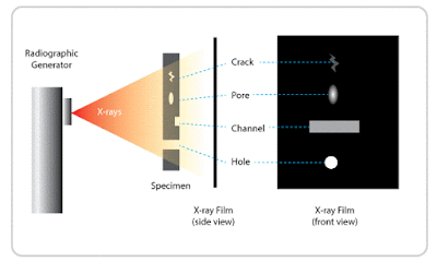
           Radiography technique is based on exposing the components to short wavelength radiations in the form of X-Rays, Gamma rays and radio-isotope welds. This method is used to check internal cracks, shrinkage cavities, slag inclusions, defects in materials and welds. These defects are of special importance designed to withstand high temperature and pressure employed in power plants, atomic reactors, pressure vessels and oil refining equipment; because they cause stress concentration which may frequently lead to part failure. Nowadays, radiography techniques are finding more extensive applications in the field of physical metallurgy and in the treatment of various diseases.
           Rays are absorbed by the materials through which they are passed in the proportion of their density. The rays, after passing through the components, show a picture on a fluorescent screen or on a photographic plate. The cracks, blow holes and cavities appear lighter, where as inclusions of impurities appear darker than the metal component. Developed photographic film show lighter and darker areas to represent the radiograph of defects in the component.


                  In X-Ray radiography, the portion of the casting where defects are suspected is exposed to X-Rays emitted from the X-ray tube. A cassette containing X-ray film is placed behind and in contact with the casting perpendicular to rays. X-rays after allowing through the blow hole in a casting, will be absorbed to lesser extent than X-rays which allowed to pass through sound metal, therefore, film appears to be more dark where defects are in line of X-ray beam. The exposed and developed X-ray film showing light and dark areas is termed as Radiograph. X-rays are useful only for small thickness material as their penetration power is less than that of gamma rays.

GAMMA RADIOGRAPHY

                The principle of detecting defects is same as X-ray radiography. Gamma rays are emitted during the disintegration of radio active material and X-rays are electromagnetic radiation.Gamma rays have shorter wavelengths and are more penetrating than X-rays. The source for gamma radiations is usually the radioactive isotopes of cobalt-60 enclosed in a special container or capsule. Gamma rays radiography give better results for thicker materials. Now a days cheap radioisotopes are available and this test can be performed in a very short time and therefore this method is becoming more popular. However, there are some limitations of this method, e.g., Handling of radioisotopes and precautions required.

Gamma-ray radiography differs from X-ray radiography in the following aspects:

  1. The apparatus for Gamma-ray radiography is very simple and less costly than X-ray unit.
  2. Unlike X-rays, Gamma rays from its source are emitted in all directions, therefore, a number of separate castings having cassette containing film, fastened to the back of each casting, are disposed in a circle around the equipment placed in a central position. This way, many castings can be radiographed simultaneously and overnight exposures may be taken without continues supervision.
  3. X-rays are better than gamma rays for detecting small defects in casting sections less than about 50 mm.
  4. Gamma rays are used for detecting defects in castings thicker than those inspected by X-rays.
  5. X-ray method is much more rapid than Gamma-ray method, it requires seconds or minutes instead of hours.    

MAGNETIC PARTICLE INSPECTION

                 This test is generally used to locate cracks and surface defects in a wide range of products. But in particular, it is employed to detect fatigue cracks at points of local high tensile strengths. The name "Magnaflux" is commonly associated with this process. This method is a relatively simple and easy technique. It is almost free from any restriction as to size, shape, composition and heat treatment of ferromagnetic substance.


              This method is restricted to magnetic materials e.g., iron, cobalt, nickel. etc. This test is based on the principle that if there is flaw in the magnetic material through which a magnetic field is allowed to pass, the lines of magnetic force or flux will be distorted near the flaw and lines of magnetic flux will be uniform for magnetic materials which are defect free.
             This test is performed by magnetising the substance and the immersing the test piece in a bath of kerosene oil containing iron oxide powder. One can also use the coloured power. If a crack or void lies across the path of the magnetic flux, each side of the crack or void becomes a magnetic pole which attracts iron powder. The accumulation of iron dust on the crack portion of the sample reveal the crack. This test can detect both internal and external defects. One can detect the cracks caused by quenching fatigue failure in welding, blow holes in castings and grinding operations by this method.


ULTRASONIC TESTING

                       The sound waves whose frequency is above the upper pitch limit of the human ear are called Ultrasonics. Ultrasonic testing and inspection is one of the most useful non-destructive methods in metal testing. Rail roads, water pipes, boilers, air craft parts of forged materials, etc., are tested for cracks, inclusions or other internal discontinuities.
                      Ultrasonic waves are usually generated by the piezoelectric effect which converts electrical energy to mechanical energy. A quartz crystal is used for the purpose.

  • The surface of casting to be inspected by ultrasonics is made fairly smooth by machining otherwise ultasonic waves can't be efficiently transmitted from the probe into the casting. Before transmitting ultrasonic waves, an oil or water film is provided between the probe and the casting surface; this ensures proper contact between them and better transmission of waves from the probe into the surface of the object to be tested.
  • For carrying out the operation, ultrasonic wave is introduced into the metal and the time intervals between transmission of the outgoing and reception of incoming signals are measured with a cathode ray oscilloscope (CRO). The time base of CRO is so adjusted that the full width of the trace represents the section being examined.
  • As the wave is sent from the transmitter, if the test piece is free from cracks, or flawless, then it reflects ultrasonic waves without distortion. If there are any flaws in the specimen, the time taken by the ultrasonic waves will be less as the reflection of these waves will be from flaw points and not from the bottom of the specimen. Cathode ray oscilloscope (CRO) is used to receive the sound signals,whose time base circuit is connected to it. Knowing the time interval between the transmission of the sound pulse and the reception of the echo signal, we can calculate the depth of the crack.

ADVANTAGES : 
  1. It involves low cost and high speed of operation.
  2. This method is more sensitive than radiography.
  3. Big castings can be symmetrically scanned for initial detection of major defects.
  4. Depth of penetration for flaw detection or measurement is superior to the other methods.
  5. Only single sided access is required.
  6. It provides flaw distance information.
  7. The minimum flaw size which can be detected is equals to about 0.1% of the distance from the probe to the detect.

DISADVANTAGES :
  1. This method of inspection is sensitive to surface roughness.
  2. Thin parts may be difficult to inspect.
  3. Linear defects oriented parallel to the sound beam can go undetected.
  4. Reference standards are often needed.

LIQUID PENETRATION TEST

                    This test is employed for detection of small defects which are very small to detect with naked eye. This test is used to detect surface cracks or flaws in non-ferrous metals. The test specimen is first thoroughly cleaned and dried before the test. A liquid penetrant is applied to the surface; This test employs a visible colour-contrast dye penetrant technique for the detection of open surface flaws in metallic and non-metallic objects. The penetrants are applied by spraying, dipping or brushing over the surface of material to be inspected. The excess penetrant is then washed or cleaned. Absorbent powder is then applied to absorb the penetrants in the cracks, voids which reveals the flaws. This test reveals flaws such as shrinkage cracks, porosity, fatigue cracks, grinding cracks, forging cracks, seams, heat treatment cracks and leaks etc., on casting, welding, machined parts, cutting tools, pipes and tubes.

                  If the fluorescent penetrant is used the developed surface must be examined under ultra violet light to see the presence of defects. This technique is used for non-porous and non-absorbent materials. Care may be taken to clean the surface so that it is free from dust, scale, etc, to have better results. penetrants are highly toxic and flammable and hence proper precautions should be taken both during use and of storage of penetrants.
              Liquid penetrant tests are simple, versatile, portable and inexpensive. The results are easy to interpret but only surface faults can be detected. If a permanent record is required a photograph or videotape or inspectors report may be kept. The use of laser scanners and digital control allows this process to be used as a mass production technique.

ELECTRICAL METHOD

                   The electrical method consist in measuring the electrical resistance of the material and then to note the variation in the electrical resistance. The variation is co-related to the physical defect. A number of electrical methods have been employed in non-destructive inspection and testing of machinery and wide variety of metallic material and parts for dimensional inaccuracies and physical defects.
                   A crack detector operates on the principle that if a crack occurs anywhere within the piece it interfaces with the flow of electric current through the metal, increasing its overall resistance. This holds true regardless of the shape of piece. Operation of the instrument consists of accurately measuring the electrical resistance of some critical machine part between two definitely established contact points, usually chosen at extreme opposite ends and of repeating the measurement at regular intervals. When successive measurements show the increase in resistance at a progressive rate, a fatigue fracture is beginning to propagate and the part should be removed from the surface.


ADVANTAGES:
  1. Detects surface and near surface defects.
  2. Test probe doesn't need to contact the part.
  3. Method can be used for more than flaw detection.
  4. Minimum part preparation is required. 

 DIS ADVANTAGES:
  • Only conductive materials can be inspected.
  • Ferromagnetic materials require special treatment to address magnetic permeability.
  • Depth of penetration is limited.
  • Flaws that lie parallel to the inspection probe coil winding direction can go undetected.
  • Surface finish and roughness may interfere.
  • Reference standards are needed for setup.

DAMPING

                    As the Measurement of damping can give information on the origin of defect such as forming of quenching cracks. For Example, an increase in damping was found in steel specimen which had been quenched. It is possible to determine the position of a crack in a cylindrical piece. When a solid specimen vibrates, its free oscillations decay when isolated from their environment. Some of the energy is always convert into heat. The various mechanisms by which this transfer of energy occurs are collectively termed as internal friction.